


2D drawings are great, but 3D takes it to a whole new dimension.
But, by adding that third dimension, we come across a problem: Since our computer screens are 2-dimensional, how do we display 3-dimensional objects on it?
It turns out, all we have to do is display the projection of that 3-dimensional object onto the x/y plane. (P.S. having some knowledge of vectors and vector math is useful when following this).
If you're unfamiliar with the term "projection", try reading this and then come back after: en.wikipedia.org/wiki/Vector_projection
Now, to project a vector onto another vector, we take the *dot product of that vector with the vector we want to project onto.
Let's imagine we have a 3-dimensional vector A⃗that represents the point (x, y, z):
A⃗ = xi + yj + zk
(i, j, and k represent unit vectors in the x, y, and z directions respectively)
So to project a vector A⃗ onto the x/y plane, what vector do we need to take the dot product of?
Well, it turns out, this is as easy as simply getting rid of the vector's z component zk.
But if we're not using the z-axis to draw the point, then why would it be useful at all? Because the z-axis allows us to manipulate the x and y axes in ways we couldn't before; for example, with the z-axis, we can rotate points around the x and y axis.
In short, the z axis interacts with the x- and y-axes to determine the final x and y coordinates of the points.
You'll see what I mean in a bit.
Let's start writing some code to make this rock-solid. We'll create a basic HTML file and add a script tag to it where we can write our JavaScript:
<!DOCTYPE html>
<html>
    <body>
        <canvas id="viewport"></canvas>
        <script>
         //Our JavaScript
        </script>
    </body>
</html>
We're not going to do anything else with the HTML, but you can see we're using HTML canvas to do this simulation.
Now let's write some boilerplate code for setting up the canvas:
//Grap a reference to the canvas and get a context
var canvas = document.getElementById("viewport")
canvas.style.border = "black 1px solid"

//Set the width and height
canvas.width = 600
canvas.height = 600

var ctx = canvas.getContext("2d")
Now let's add some settings to control the colors and sizes of our nodes and edges, and set up our units correctly:
var colors = {
    node: "green",
    edge: "blue"
}

var NODE_SIZE = 3
var PIXELS_PER_UNIT = 100
Next, I've written a couple drawing functions so we don't have to worry about working with canvas, and can instead focus on the theory:
//Some functions to make things easier
function circle(x, y, radius) {
    ctx.beginPath()
    ctx.arc(x, y, radius, 0, 2 * Math.PI)
    ctx.fill()
}

function line(x1, y1, x2, y2) {
    ctx.beginPath()
    ctx.moveTo(x1, y1)
    ctx.lineTo(x2, y2)
    ctx.stroke()
}
Ok, now let's create two classes that we'll use to represent our points. The first is the Node class, which basically represents a vertex of the mesh:
class Node {

    constructor(x, y, z) {
        this.x = x
        this.y = y
        this.z = z
    }

    draw() {

        ctx.fillStyle = colors.node
        circle(this.x * PIXELS_PER_UNIT, this.y * PIXELS_PER_UNIT, NODE_SIZE)

    }

}
It's a very simple class: basically we're storing some values, and adding a draw method which will draw a circle in the appropriate place (the * PIXELS_PER_UNIT just converts our units into pixels to draw).
Next, we have the Edge class, which connects two Nodes:
class Edge {

    constructor(node1, node2) {
        this.node1 = node1
        this.node2 = node2
    }

    draw() {

        ctx.strokeStyle = colors.edge
        line(this.node1.x * PIXELS_PER_UNIT, this.node1.y * PIXELS_PER_UNIT, this.node2.x * PIXELS_PER_UNIT, this.node2.y * PIXELS_PER_UNIT)

    }

}
All we're doing here is storing two nodes, and defining a function for drawing them.
Now, let's define some nodes. The values I've entered here represent a cube:
//Now let's make a cube
var nodes = [
        new Node(-1, -0.5, -1), //Top-Back-Left
        new Node(1, -1, -1), //Top-Back-Right
        new Node(1, -1, 1), //Top-Front-Right
        new Node(-1, -1, 1), //Top-Front-Left
        new Node(-1, 1, -1), //Bottom-Back-Left
        new Node(1, 1, -1), //Bottom-Back-Right
        new Node(1, 1, 1), //Bottom-Front-Right
        new Node(-1, 1, 1) //Bottom-Front-Left
]
We have a node for the top-back-left, top-back-right, top-front-right, top-front-left, bottom-back-left, bottom-back-right, bottom-front-right, and bottom-front-left vertices of the cube.
Then, we define the edges to connect the appropriate nodes:
var edges = [
        new Edge(nodes[0], nodes[1]), //Top-Back-Left -> Top-Back-Right
        new Edge(nodes[0], nodes[4]), //Top-Back-Left -> Bottom-Back-Left
        new Edge(nodes[0], nodes[3]), //Top-Back-Left -> Top-Front-Left
        new Edge(nodes[1], nodes[5]), //Top-Back-Right -> Bottom-Back-Right
        new Edge(nodes[1], nodes[2]), //Top-Back-Right -> Top-Front-Right
        new Edge(nodes[3], nodes[2]), //Top-Front-Left -> Top-Front-Right
        new Edge(nodes[3], nodes[7]), //Top-Front-Left -> Bottom-Front-Left
        new Edge(nodes[2], nodes[6]), //Top-Front-Right -> Bottom-Front-Right
        new Edge(nodes[4], nodes[5]), //Bottom-Back-Left -> Bottom-Back-Right
        new Edge(nodes[5], nodes[6]), //Bottom-Back-Right -> Bottom-Front-Right
        new Edge(nodes[6], nodes[7]), //Bottom-Front-Right -> Bottom-Front-Left
        new Edge(nodes[7], nodes[4]) //Bottom-Front-Left -> Bottom-Back-Left
]
You can read through all the comments if you want to verify; otherwise just trust me, this makes a cube.
Now, we'll define one more class: the Mesh class. This class takes all the nodes and edges, and draws them:
class Mesh {

    constructor(nodes, edges) {
        this.nodes = nodes
        this.edges = edges
    }

    draw() {

        for (var i = 0; i < this.edges.length; i++) {
            this.edges[i].draw()
        }

        for (var i = 0; i < this.nodes.length; i++) {
            this.nodes[i].draw()
        }

    }

}
Pretty basic. Now, let's take everything we've done, and draw it on the screen:
First, we want to display the cube in the center of the screen, which means we want the origin (0, 0) to be at the center of the screen:
ctx.translate(canvas.width/2, canvas.height/2)
Next, we'll define an instance of our mesh, and call the draw function:
var cube3D = new Mesh(nodes, edges)
cube3D.draw()
Hooray! We have a cube...or...just a square?
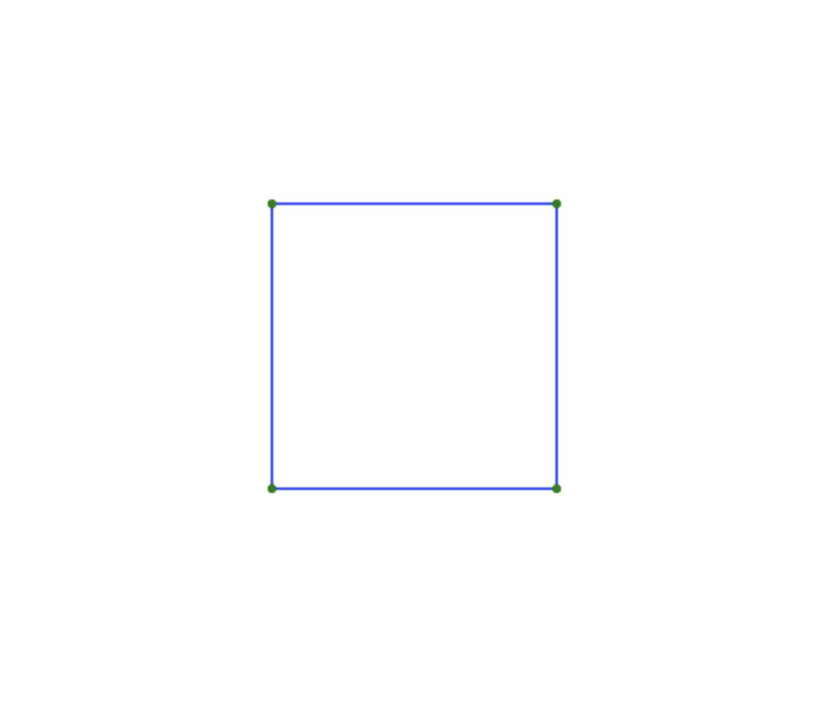
Actually, this is our cube, but because we're looking at it straight from the side, we only see it as a square. So, to make this a bit more interesting, we need to rotate it!
For that, we're going to need to do some math.
Because we're in three dimensions here, there are three axes we could rotate around: x, y, and z.
It turns out that x and y are the most interesting axes to rotate around, so we'll do the math for those. However, it's pretty simple to apply the math from the x and y axes to the z axis if you should need to.
So, let's imagine that we have a point, which we want to rotate around the y axis. If we look down on it from above, we'll see the x and z axes, and we'll plot that point:
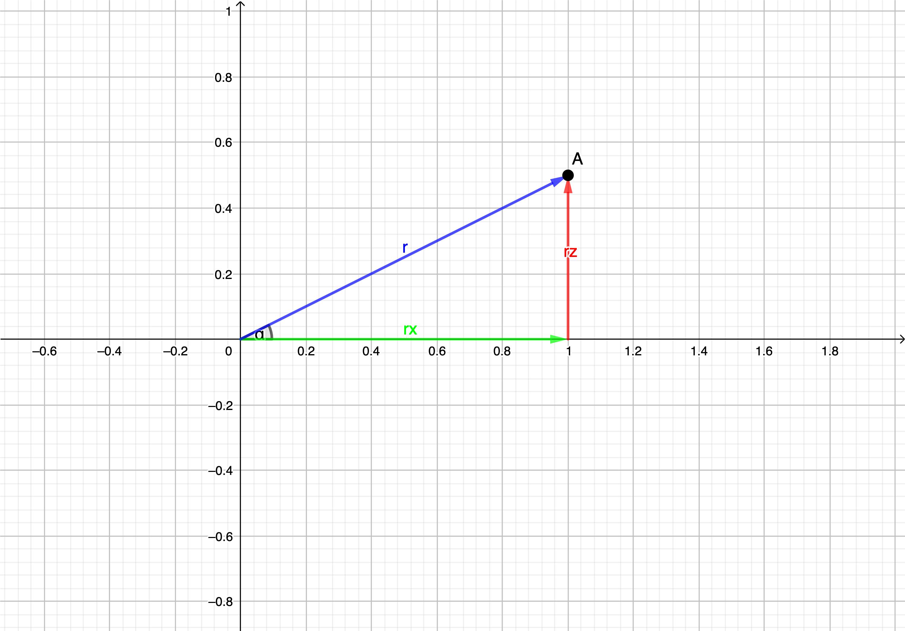
Now, we know from vector conversions and/or the polar coordinate system, that:
x = r * cos(a)
and
z = r * sin(a)
Where x is the x coordinate of the point, z is the z coordinate of the point, and "a" is the angle between the vector represented by this point and the x axis.
Now let's say we want to rotate that point around the y axis by an angle b. Then we have:
x2 = r * cos(a + b)
z2 = r * sin(a + b)
Now we can use trig identities to do this:
x2 = r * cos(a) * cos(b) - r * sin(a) * sin(b)
z2 = r * sin(a) * cos(b) + r * cos(a) * sin(b)
This looks way more complicated than before, but if you look closely, you'll see multiple occurrences of r * sin(a) and r * cos(a).
And if you remember:
x = r * cos(a)
z = r * sin(a)
Which means we can substitute those in where they occur in our equations:
x2 = x * cos(b) - z* sin(b)
and
z2 = z * cos(b) + x * sin(b)
That's something we can write in code!
Let's create a rotateY function in our Mesh class:
rotateY(theta) {
        //For each node...
        for (var i = 0; i < this.nodes.length; i++) {
            //Update the x and z coordinates according to the new angle
            var x2 = this.nodes[i].x * Math.cos(theta) - this.nodes[i].z * Math.sin(theta)
            var z2 = this.nodes[i].z * Math.cos(theta) + this.nodes[i].x * Math.sin(theta)

            this.nodes[i].x = x2;
            this.nodes[i].z = z2;
        }

    }
The math for rotating x is so similar that I'm confident you could derive it yourself, so I'll just give you the equations for that:
z2 = z * cos(b) - y * sin(b)
y2 = y * cos(b) + z * sin(b)
So we'll make a rotateX function in our Mesh class as well using these equations:
rotateX(theta) {

        for (var i = 0; i < this.nodes.length; i++) {

            var z2 = this.nodes[i].z * Math.cos(theta) - this.nodes[i].y * Math.sin(theta)
            var y2 = this.nodes[i].y * Math.cos(theta) + this.nodes[i].z * Math.sin(theta)

            this.nodes[i].z = z2;
            this.nodes[i].y = y2;
        }

    }
And now let's call those functions before drawing the cube:
cube3D.rotateY(Math.PI / 4) //rotateY 45 deg
cube3D.rotateX(Math.PI / 4) //rotateX 45 deg
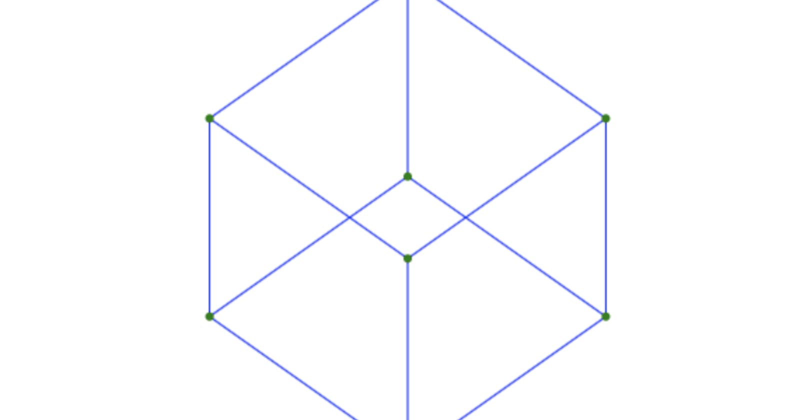
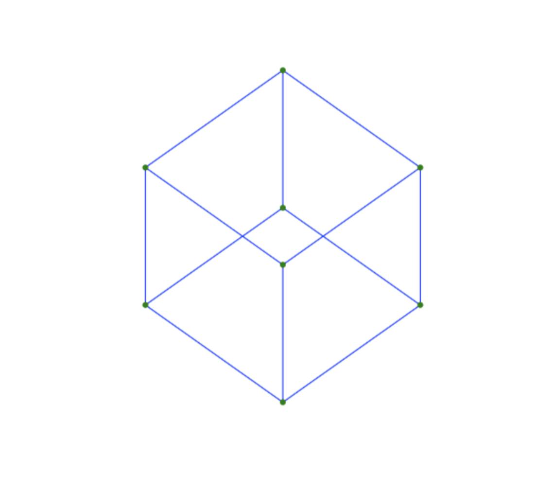
And there you have it! A beautiful wireframe cube!
If you want to look at my code, you can find it on github here: github.com/naclcaleb/3D-with-JavaScript Or play around with it on codepen here: codepen.io/naclcaleb/pen/BaBrqJe
And now a quick note on going further:
With this, you can make meshes with as many nodes or edges as you want, but at some point or another, you're going to want to add faces.
On the surface, you might think you can just draw a quadrilateral connecting the right nodes together. However, this will not work; you have two problems:
- You have to draw the faces in the right order, so the "front" ones are drawn last, and the "back" ones are drawn first.
- You have to shade the faces so they don't look like a 2D shape.
These two problems are definitely beyond the scope of this post, but perhaps I will make another post covering those at some point.