


Raspberry Pi Home Automation with Google Assistant integration — Part 2 (Hardware)


Part 1: Raspberry Pi Home Automation with Google Assistant integration — Part 1 (Software)
By now, you have already followed the software part 1 of this series. Now let’s get to the hardware part of the project.
We’ll need the following:
- Relay Module
- Jumper cables (female to female)
- Electrical wires in at least 2 colours
- Wire Cutters
- Wire Strippers
- Screwdriver
Understanding the GPIO pins on the Raspberry Pi
The Raspberry Pi is quipped with an array of GPIO pins some of which can be programmed
$ pinout
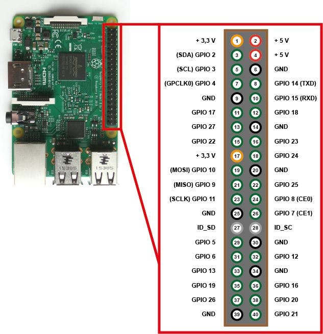
In Part 1, the config uses GPIO pins 3, 4 and 7. You can edit
To change pin config, edit https://github.com/sidhantpanda/raspberry-pi-home-backend/blob/master/custom_modules/relayControls/config.js.
Delete the file at /home/pi/buttons.json
$ rm /home/pi/buttons.json
Understanding the I/O pins on the Relay Module
Depending upon the number of switches your relay module contains, you can control up to 2/4/8 or even more devices. We’ll use as many GPIO pins on the Pi and control the relay with logical 1 and 0.
We’ll connect the common pin of the relay switch to the live wire behind our switchboard on the wall. Next we’ll connect the neutral wire behind the physical switch on the board to the normally closed pin of the same switch.
To understand more about common and normally closed pins, read this small guide randomnerdtutorials.com/guide-for-relay-mod... This what the basic electrical circuit looks like.
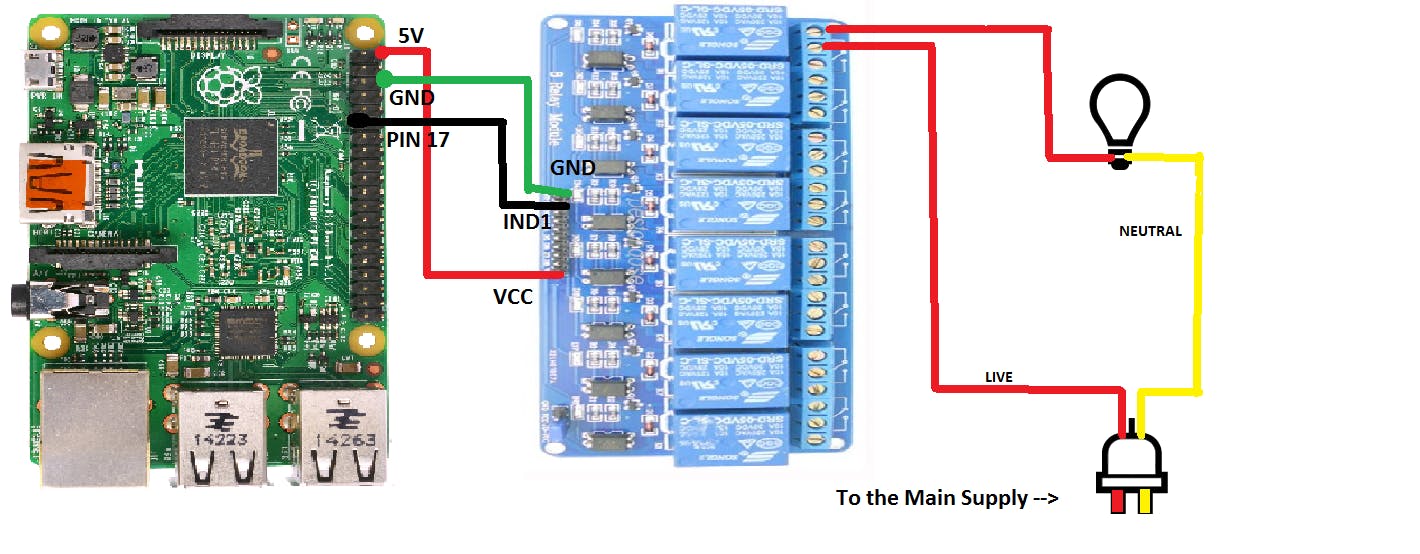
This is what the circuit diagram looks like fo the pins. Connections:
- VCC on relay module to a 5V pin on the Raspberry Pi.
- GND on relay to GND on Raspberry Pi
- IND1 to GPIO 3
- IND2 to GPIO 4
- IND3 to GPIO 17
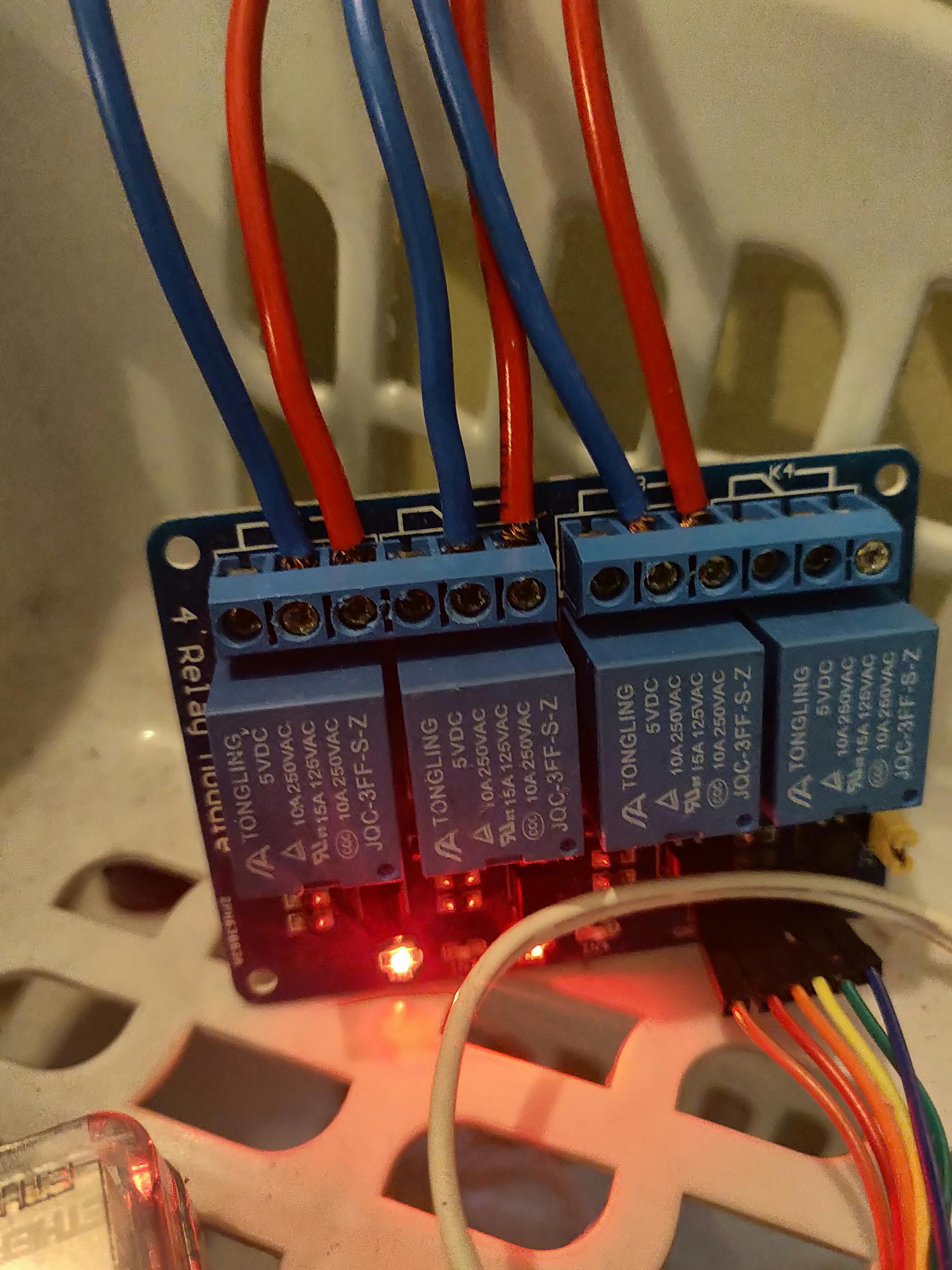
This is how I’ve wired up my relay module:
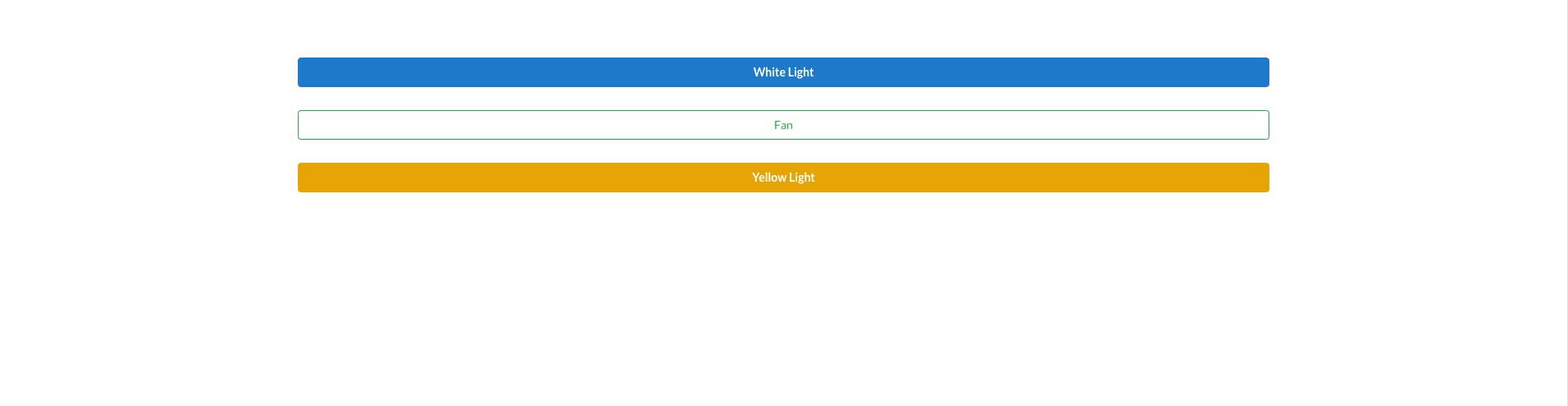
Alright, you’re all set with NodeJS server + React Frontend for your Raspberry Pi + Relay Module configuration!
The frontend is exposed via the 80 port on the raspberry pi. Find the local IP for your raspberry pi and connect to it. Assuming your Pi is at 192.168.1.10, open http://192.168.1.10/ on a web browser in the same local network and the dashboard with fire up:
Next, we’ll see how we can use Google Home to control the switches. The next step requires you to have an Google Assistant capable device (Android phone, Google Assistant speakers, iOS app etc) and is completely optional. You can control the switches from any browser in your local network currently.
Part 3: Raspberry Pi Home Automation with Google Assistant integration — Part 3 (Assistant integration)